Contents
Index
NT Unit Title Schemes - Strata Subdivisions
Step By Step Instructions
A strata subdivision consists of a number of "cubic spaces" (lots) and in a multi storied structure these may be on different levels.
Each strata title may be individually owned except for those labelled "Common Property"
The Common Property lots often contain special use areas (Stairs, lifts, hallways etc)
If the subdivision is all on one level then it can be treated as a normal subdivision
Multi storied strata subdivisions have to be treated differently as shown in this document.
A strata unit may have a number of individual lots and these can be treated in the same way that multi-polygon lots
are handled by adding Pt1, Pt2 etc to the unit number for each lot.
So if unit number 12348 is comprised of four lots (a car park, storage, laundry and living area)
They will be called 12348Pt1, 12348Pt2, 12348Pt3, 12348Pt4.
Each lot is considered to be a cubic space "Floating" above the base lot.
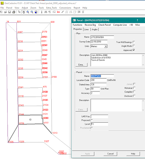
Common property lots have the words "Common Property" entered in the parcel description field
The floor level is entered in the "Level" field which is at the bottom of the parcel area in the Admin dialogue box.
To standardize this procedure, the ground floor should be called "G", basements should be shown as B1, B2, B3 etc
Mezzanines M1, M2, M3 etc., and the upper floors as F1, F2, F3 etc.
As well as showing lot boundaries, a strata plan may show the location of lifts, hallways, balconys, stairs etc.
These are special use areas inside a parcel and can be treated in the same way that easements are managed.
They are entered as a polygon after the main polygon in their parcel and are alloced a line type to indicate their special use.
This line type also needs to be set up in the "lineTypes" area of the config file
In the Northern Territory, parcels on the ground floor (including the common property) will be treated as normal parcels
in the cadastral network. Connections to reference marks and other boundary definition data should be attached to the
parcels at this level.
In Geocadastre, the ground floor dimensions can be included or excluded from the adjustment equations.
The dimensions from parcels at all other levels will not be included, however they will be used to move the corners on those levels
to maintain their relative position to original lot surround.
In the display menu there is an option to either either display or hide the strata parcels.
If they are displayed, there is an option to show the boundaries at a selected level.
If you use "Select parcel by windows", only the visible parcels in a strata subdivision will be selected
Strata plans are mostly diagrammatic, and they also are very repetitious with many of the lots being identical in shape and size.
There are various ways that the lot dimensions can be entered into Geocadastre
If dimensions are shown on the strata plan, they can be used to generate the lots as with any subdivision.
If some of the dimensions are missing, they can be scaled off the plan by blowing the plan image up to a suitable scale on the screen
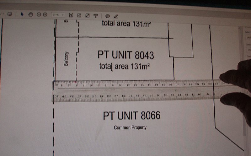
Here, with the image scale at 221%, one centimetre equals one metre on the screen and dimensions san be scaled to the nearest 100mm.
.
Alternately, an image of the plan drawing can be superimposed on the parcel surround and the lines digitized using the mouse.
If any line in a strata lot is digitized or scaled from the drawing, the accuracy of that lot should be set to 6.
If there is an architectural file of the building in DXF format, this can be used to create most of the lots
see Read DXF File
Connections are required between parcel polygons and the outside surround so that coordinates can be calculated for all corners
when the outside surround is joined to the cadastral network.
These connections may be shown on the plan or they may have to be digitized from the plan.
In Geocadastre, you can either display or hide the strata parcels.
If they are displayed, there is an option to show the boundaries at a selected level.
It is best to work floor by floor with each floor being assembled separately as a group of parcels.
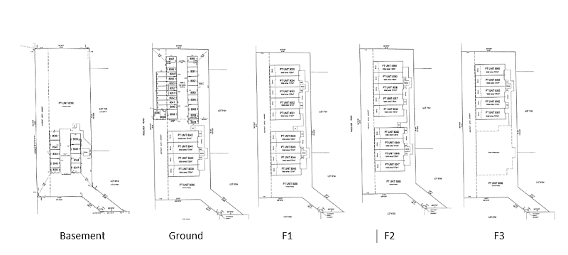
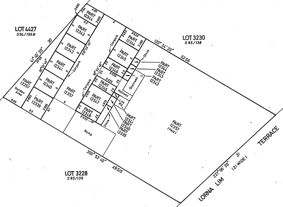
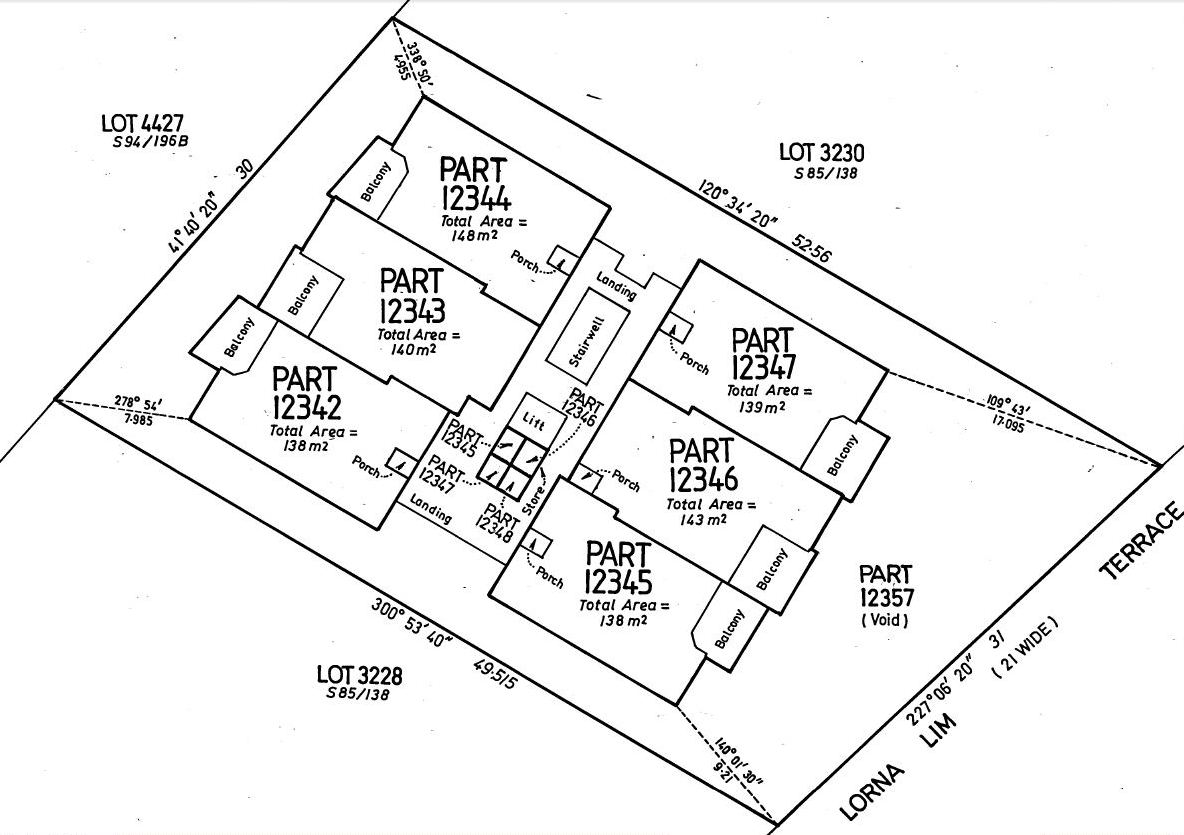
Below is a picture of the lots from a strata subdivision plan and these will be used to show the processes that can be used
Start the job by entering the outside boundary for the basement floor, call the lot "working",
then use “Extra tools/Duplicate Strata Floor” to also make the first floor surround.
The garage lots are of two sizes so make one of each them and use the “duplicate” option to create all the rest.
Join the basement lot into some blank space, then join in all of its garage lots.
The common property lot for this floor is the area that is left after all of the garage lots have been excluded.
Unjoin this floor as a group and use "New Parcel for Group" to enter the common property lot.
The lines for this lot can be generated by using the mouse to select each corner in succession around the lot.
Join the group to the network, then unjoin 'Working' parcel.
The "Common Property" parcel will generally also include all the main lot boundaries, so this lot is now unnecessary.
The residential units on the other floors are all the same size and there are two shapes one being the mirror image of the other.
The lots are parallel to the side boundaries, so make a lot for each shape using scaled dimensions and duplicate a number of copies of each.
Join the ground floor to open space and join in its main parcels, then duplicate that floor to start the first floor.
Back on the ground floor, join in the garage lots, unjoin it as a group and use "New Parcel for Group" to enter the common property lot.
Join the group to the network, then unjoin 'Working' parcel.
The process for the first floor is similar to that used for the ground floor.
Join to open space, join in the extra lots, unjoin as a group and use the mouse to digitize the common property lot.
Join the group to the network, then unjoin 'Working' parcel.
Duplicate the floor to create the second floor and the third floor.
For the third floor, join to open space, unjoin and delete the extra lots, then unjoin as a group and use the mouse to digitize the common property lot.
Join the group to the network, then unjoin 'Working' parcel.
Another example using UTS2014/010 follows:
At this level some lots are dimensioned and some not so the data will have to be a combination of measurements and digitized measurements.
It is easier to enter the dimensioned parcels first, followed by those lots which have to be digitized.
Ground Floor
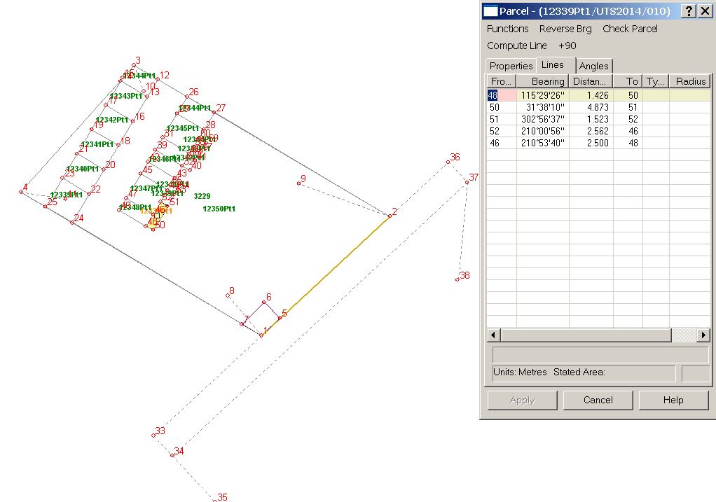
At this level the car parking areas can be entered from dimensions show on the plan.
The connections along the southern boundary and up to the south west corner of PART12351 should also be added to the ground floor parcels.
The "Living Area" parcels (PART12339 - PART12341) can be digitized.
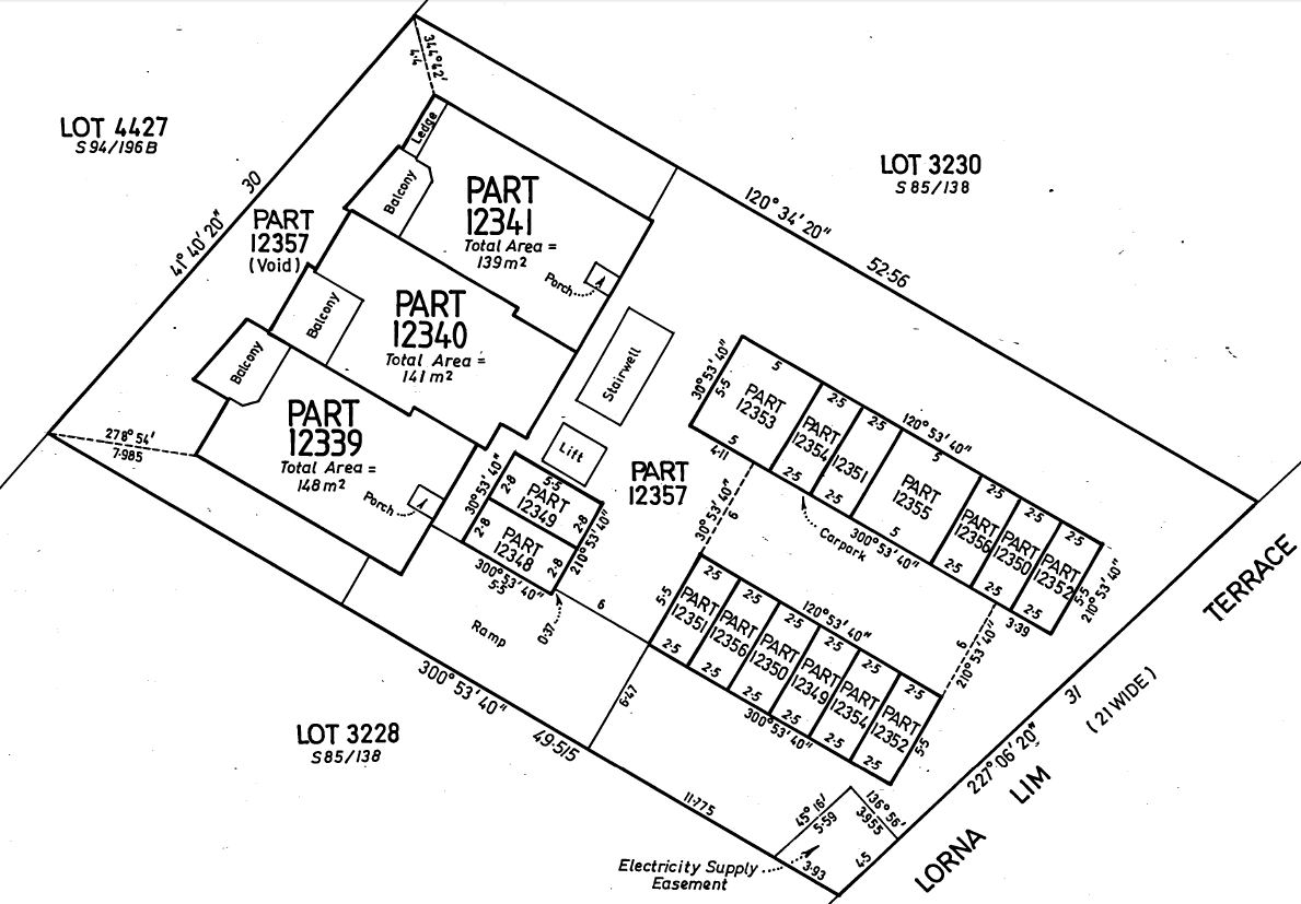
Ground Floor
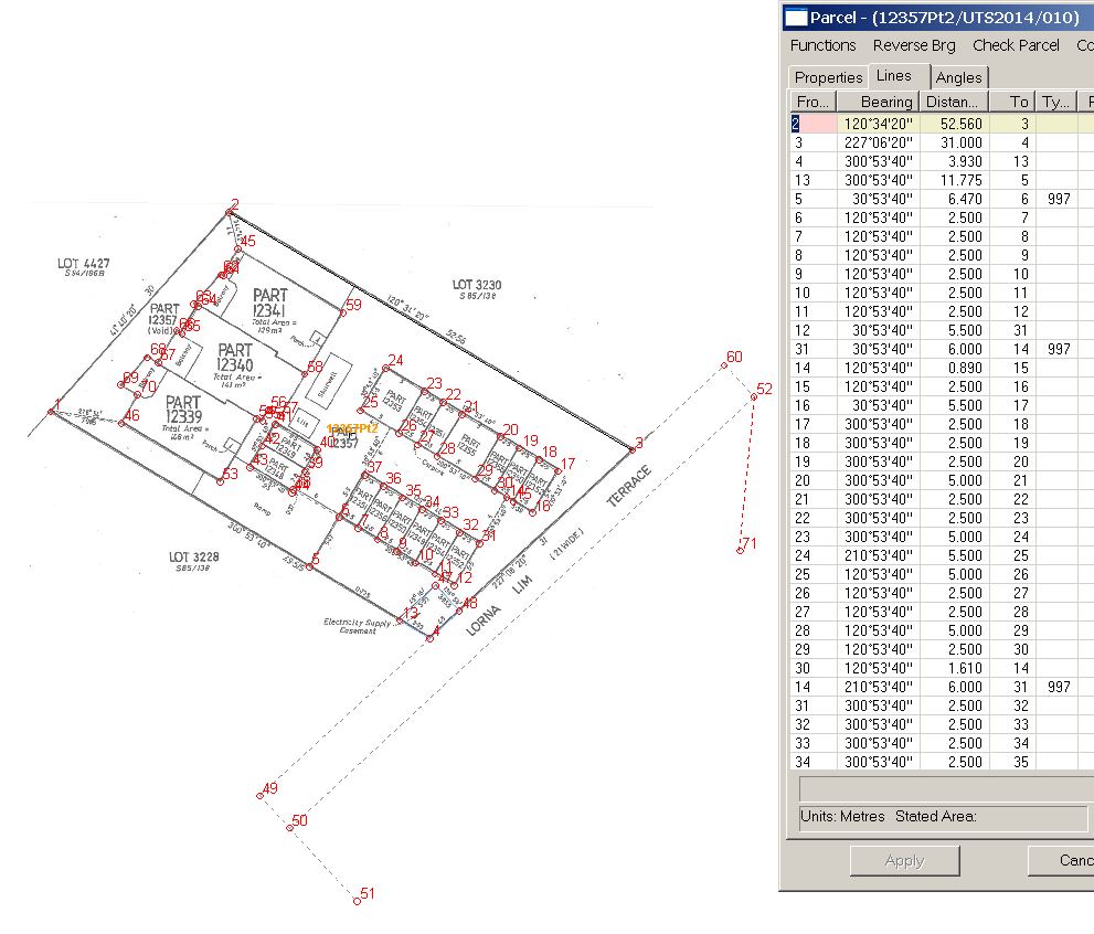
The Ground Floor common property with the plan image superimposed on the data entry screen
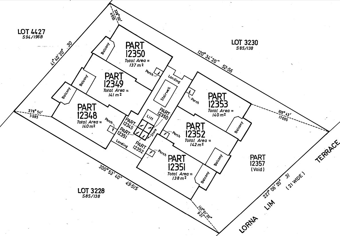
First Floor
The Ground, First, Second and Third floors share common parcel shapes for the residential lots.
These lots can be generated by using the "Duplicate Parcel" tool.
It will detect that the duplicate parcel is part of a group of strata lots and create duplicate parcels in that group.
There are two other connections to the structure from the south-east and north-west corners.
These could be added to the ground floor common property parcel before starting on the upper floors so that those building corners are already located.
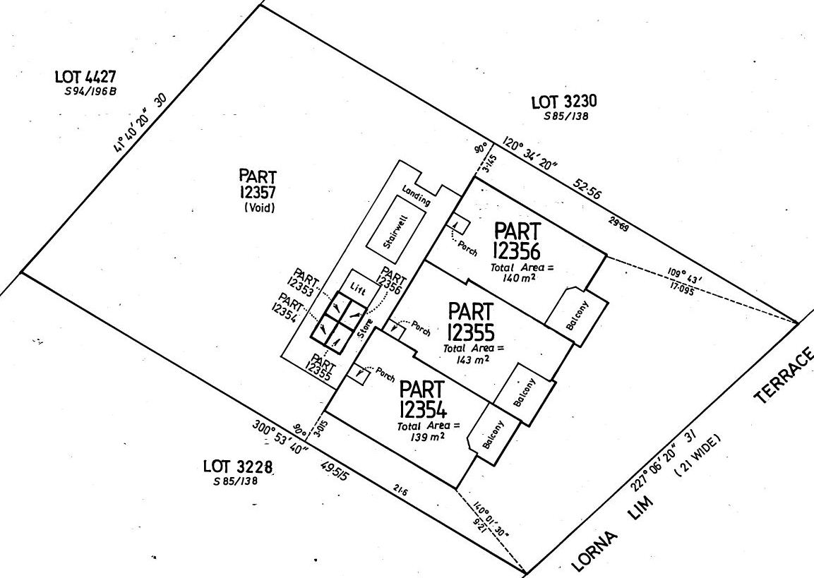
Second Floor
Third Floor
How to do a UTS - Step By Step
This procedure is used when the floor layout is unique or different to any floor below it.
- Make jpg files of the pdf plan for each floor so that they can be used for superimposition in Geocadastre.
(Can use Alt/Printscreen and paste into picture viewer and save jpg file.)
- Enter the surround parcel at Ground level with any external and internal connection lines
- Duplicate the parcel. Name it 'Working', remove external connections, Join it into a blank space.
- Join in any parcels that have been created from scaled dimensions.
- Unjoin all the parcels on the floor as a group.
- Right click on any parcel on the floor, New Parcel for Group
- Set Lot no, if digitising set acc=6
- Enter Floor no - Ground, F1, F2...
- Set up image for digtising. Toolbar/Image - orient it to the Working parcel.
- Enter/digtise all the remaining units on that Level. Create connections to Working parcel if not present.
- For the NT, if the 'Diamond/circle' parcels exist, unjoin them and delete them
- Join the group to the network, then unjoin 'Working' parcel
- Repeats steps 4 - 9 as required for the next floor, change Working Plan No if necessary.
Duplicate Floors
This procedure can be used if some or all of the parcels are exactly the same from one floor to another.
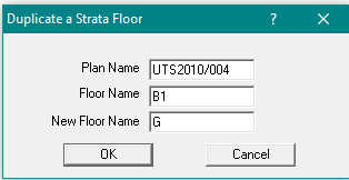
- select "Tools/duplicate Strata/UTS Plan"
- Enter the plan, the floor that is to be copied and the new floor name
- Click on the OK button. If several floors are identical, you can duplicate again and again to generate the parcel for each floor, close the Duplicate option.
- If there are unwanted lots on the floor, join the group to a blank area of the screen, unjoin the unwanted lots and then unjoin the rest as a group
- Right click on one of the new parcels and select "properties". All the lots on the floor will be displayed with the selected lot highlighted
- Change the lot number if required, then successively click on each lot on the screen and change its lot number if needed.
- When all of the lot numbers have been changed, hit the "Apply" button to save all the changes.
Tips
Non-Duplicate Floors
If a floor has a different layout for the units, they may not easily relate to the floors below
If the units are drawn in the surround with no dimensions or connections, us this approach.
- Make a copy of the Surround Parcel, name it 'Working'
- Remove any external traverses or connections or easements
- Keep or add any internal connections available as 999 connections
- Right click on 'Working' in Parcel explorer, New Parcel in Group - Opens the parcel in the parcel editor, ready for a new parcel
- Use Image Toolbar button to open jpg image of the floor and orient it using the surround points
- Enter first parcel number, area, acc=6 and floor F3,F4 etc.
- Lines tab - click on from pt, you need to click on an existing point first, say a surround corner pt
- Now click on points on the selected parcel, clockwise, until it closes. Add a connection back to the start surround point
- Now delete the first line, from surround pt to first parcel point
- When finished press Accept button
- You can now enter admin data form 2nd parcel, or Cancel to exit. Do not exit until all parcels on the floor are added to the group.
- When the floor group is complete, exit and check the parcels are all in Parcel Explorer and are correct.
- Try to get another connection to a surround corner from another parcel
- Right click on one of the new parcels in Parcel explorer, Join
- Join the floor to the Surround first and then you can join any obvious internal common points